We use cookies to enhance site navigation, analyze usage, and support our marketing. By clicking “Accept All & Continue,” you agree to our use of these technologies.
We and our partners use information collected through cookies and similar technologies to improve your experience on our site, analyse how you use it and for marketing purposes. Because we respect your right to privacy, you can choose not to allow some types of cookies. However, blocking some types of cookies may impact your experience of the site and the services we are able to offer. In some cases, data obtained from cookies is shared with third parties for analytics or marketing reasons. You can exercise your right to opt-out of that sharing at any time by disabling cookies.
These cookies and scripts are necessary for the website to function and cannot be switched off. They are usually only set in response to actions made by you which amount to a request for services, suchas setting your privacy preferences, logging in or filling in forms. You can set your browser to block oralert you about these cookies, but some parts of the site will not then work. These cookies do not store any personally identifiable information.
Analytics
These cookies and scripts allow us to count visits and traffic sources, so we can measure and improve the performance of our site. They help us know which pages are the most and least popular and see how visitors move around the site. All information these cookies collect is aggregated and therefore anonymous. If you do not allow these cookies and scripts, we will not know when you have visited our site.
Embedded Videos
These cookies and scripts may be set through our site by external video hosting services likeYouTube or Vimeo. They may be used to deliver video content on our website. It’s possible for the video provider to build a profile of your interests and show you relevant adverts on this or other websites. They do not store directly personal information, but are based on uniquely identifying your browser and internet device. If you do not allow these cookies or scripts it is possible that embedded video will not function as expected.
Marketing
These cookies and scripts may be set through our site by our advertising partners. They may be used by those companies to build a profile of your interests and show you relevant adverts on other sites. They do not store directly personal information, but are based on uniquely identifying your browser and internet device. If you do not allow these cookies and scripts, you will experience less targeted advertising.
Facebook Advanced Matching
Facebook Advanced Matching can improve ads attribution and conversion tracking. It can help us reach better-targeted custom audiences through our ads. When possible, we will share with Facebook hashed information like your name, phone, email, or address.
Facebook CAPI
Facebook Conversion API Events (CAPI) help us better understand how you interact with our websites. They allow us to measure the impact of our ads on the website's conversions and they improve ads targeting through custom audiences. When possible, we might share with Facebook information like name, email, phone, address.
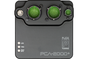
The PLEX trade discount is provided to professional tuners, engine builders, racing engineers and pro racers, who provide proof of profession. Trade discount ranges from 5-15% depending on the product and order quantity/value. Group buying is not allowed. The PCA-2000+ system is excluded.
The trade discount is NOT provided to semi-professionals, or amateur tuners/racers/engineers. Please provide us the below information to verify your request and send you a quote/pro-forma invoice. We will get in touch with you latest within 24 hours!
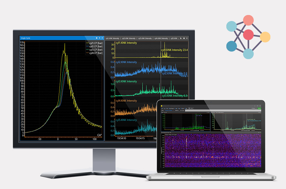
Thank you for your interest in our New PCA-2000 Combustion Analysis & Logging System!
The PCA-2000Plus is a built-to-order product, composed of various HW, FW, SW and sensor options which can be combined to match different tuning frameworks, applications and budget levels.
To be able and provide you with a meaningful quote we would need to receive the below information. The more specific your feedback is the more tailor made our quote will be.
Thank you for reaching out to us. Here, you can share your can freely share with us your
questions, suggestions, feedback, or technical/support inquiries.
Please fill out the form below, and we will get back to you with additional product and pricing information, along with an invitation to discuss potential cooperation in greater detail.

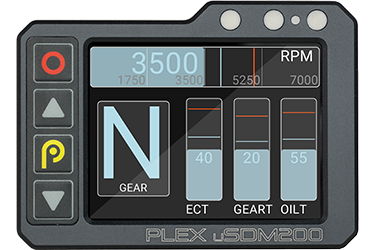
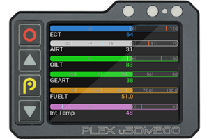


 2.8” uSDM-200
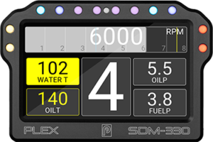
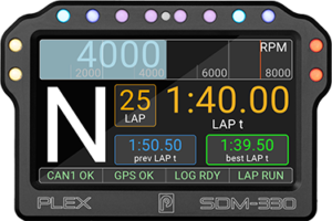
 4.3” SDM-330
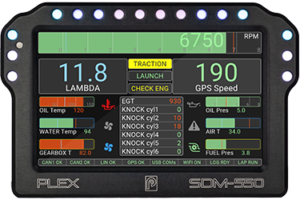
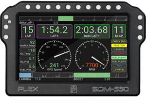
 5” SDM-550
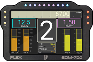
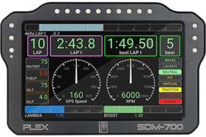
 7” SDM-700R
 uSDM-200-DL/G
 SDM-330-DL/G
 SDM-550
 SDM-700R
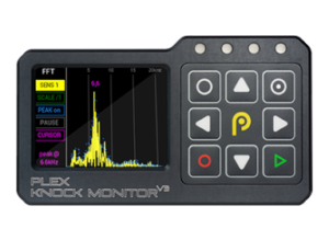
 Knock Monitor V3
 PCA-2000Plus
 PLEX KNOCK MONITOR V3
 PLEX PCA-2000Plus
 Device Configuration SW
 PCA-2000Plus System
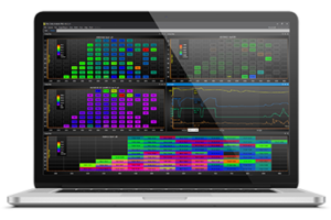
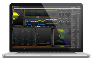
 PCA-WIN 2.0 SW
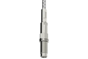
 Pressure Sensors
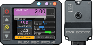
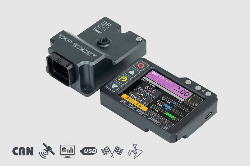
 PLEX PBC v2 KIT
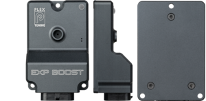
 PLEX EXP-Boost
 PLEX PDA-WIN 2.0 SW
 PLEX PDA-WIN PRO 2.0 SW
 Combustion Analysis SW