QUICK INFO:
This optional installation step is necessary when one wants to connect the Plex Knock Monitor either to an ecu, a dynamometer or an external warning light.
ANALOG OUTPUT
CONNECTOR
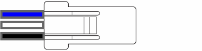
blue: knock level analog output
white: knock counter analog output
black: analog output ground
1. ECU CONNECTION
For "Viewing / Recording"
STEP 1
Connect the Knock Monitor Analog Output 1 ----> ECU 0-5V Analog input
STEP2
Configure function in menus 4.2 and 4.3
For "Ignition Knock Retard"
STEP 1
Connect the Knock Monitor Analog Output 2 -----> ECU 0-5V Analog input
STEP 2
Configure output as "ECU RETARD" in menu 4.4
STEP 3
Configure ecu to retard timing with "RISING" voltage:
Example for ECU configuration:
0V 0deg
1V -2deg
2V -4deg
3V -6deg
4V -8deg
2. DYNAMOMETER CONNECTION
STEP 1
Connect the Knock Monitor Analog Output 1 ----> Dynamometer 0-5V Analog input
STEP 2
Configure function in menus 4.2 and 4.3
STEP 3
Connect Knock Monitor Analog Output 2 ----> Dynamometer 0-5V Analog input
STEP 4
Configure function in menus 4.4 as "AUTO RESET"
3. EXTERNAL WARNING LIGHT CONNECTION
POWER + WARNING OUTPUT CONNECTOR
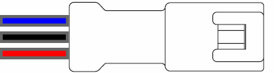
blue: ext warning
black: ground
red: +6...15volt power
Required Action
- Connect the blue "EXT WARNING" wire to an external warning light or buzzer. The output is of pull to ground type and has a max capacity of 500mA.
The external warning light will then be activated simultaneously with the red warning led.